COMPSCI 184 Project4: ClothSim
a real-time simulation of cloth using a mass and spring based system
Part 0: Project overview
In this project, I’ve implemented a real-time simulation of cloth using a mass and spring based system. Started out with masses and springs, I build grid of point masses and implemented 3 type of constraints(structual, shearing and bending) presented as strings between the point masses. Next, I implemented easy simulation with classic Newton’s law F = ma, Hooke’s law for forces on masses, verlet integration for new point mass positions and Provot’s study to ensure spring’s length is at most 10% greater than its rest_length at the end of any time step. Then it’s the collision handling with spheres and flat surfaces. Followed with self-collision handling which makes the falling fabric more realistic so that it won’t overlap unnaturally. Finally, I use GLSL to implement a lot of different vertex shaders and fragment shaders: diffuse shading, blinn-phong shading, texture mapping, bump mapping, displacement mapping and mirror-like environment-mapped reflection.
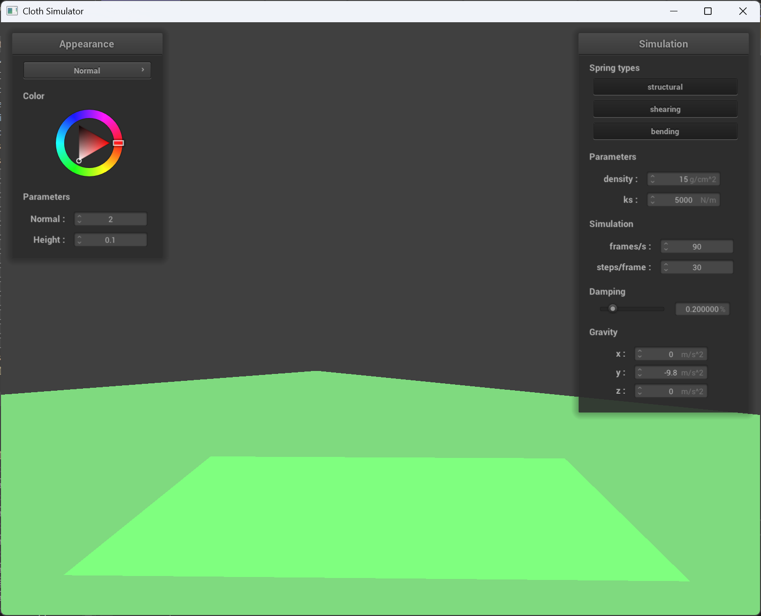
Part 1: Masses and springs
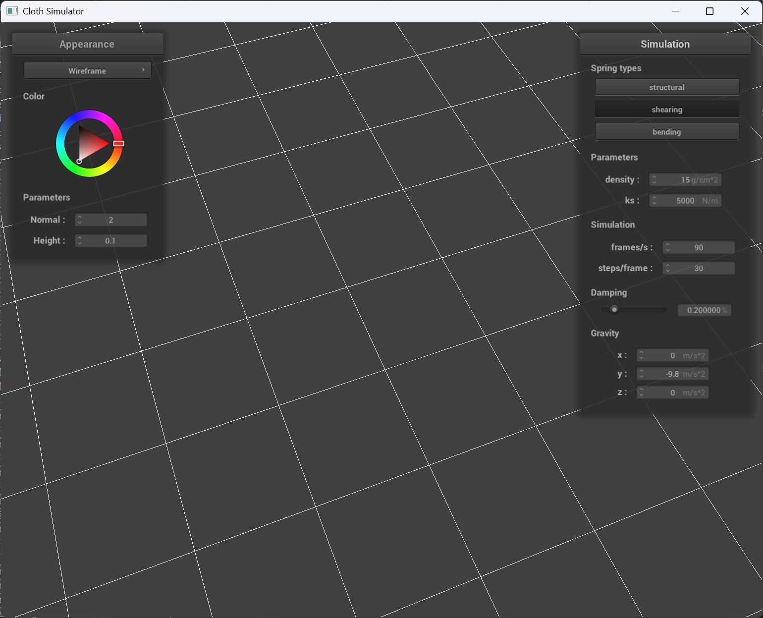
Some screenshots of scene/pinned2.json
You can also treat the picture w/ all constraints below as the third view.
 |
 |
|---|---|
| View 1 | View 2 |
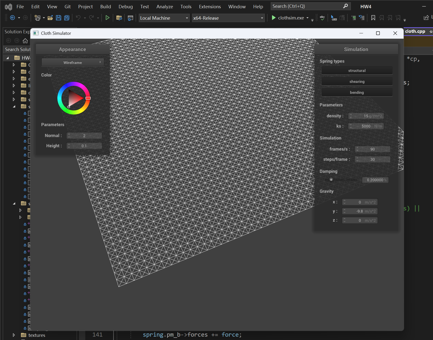
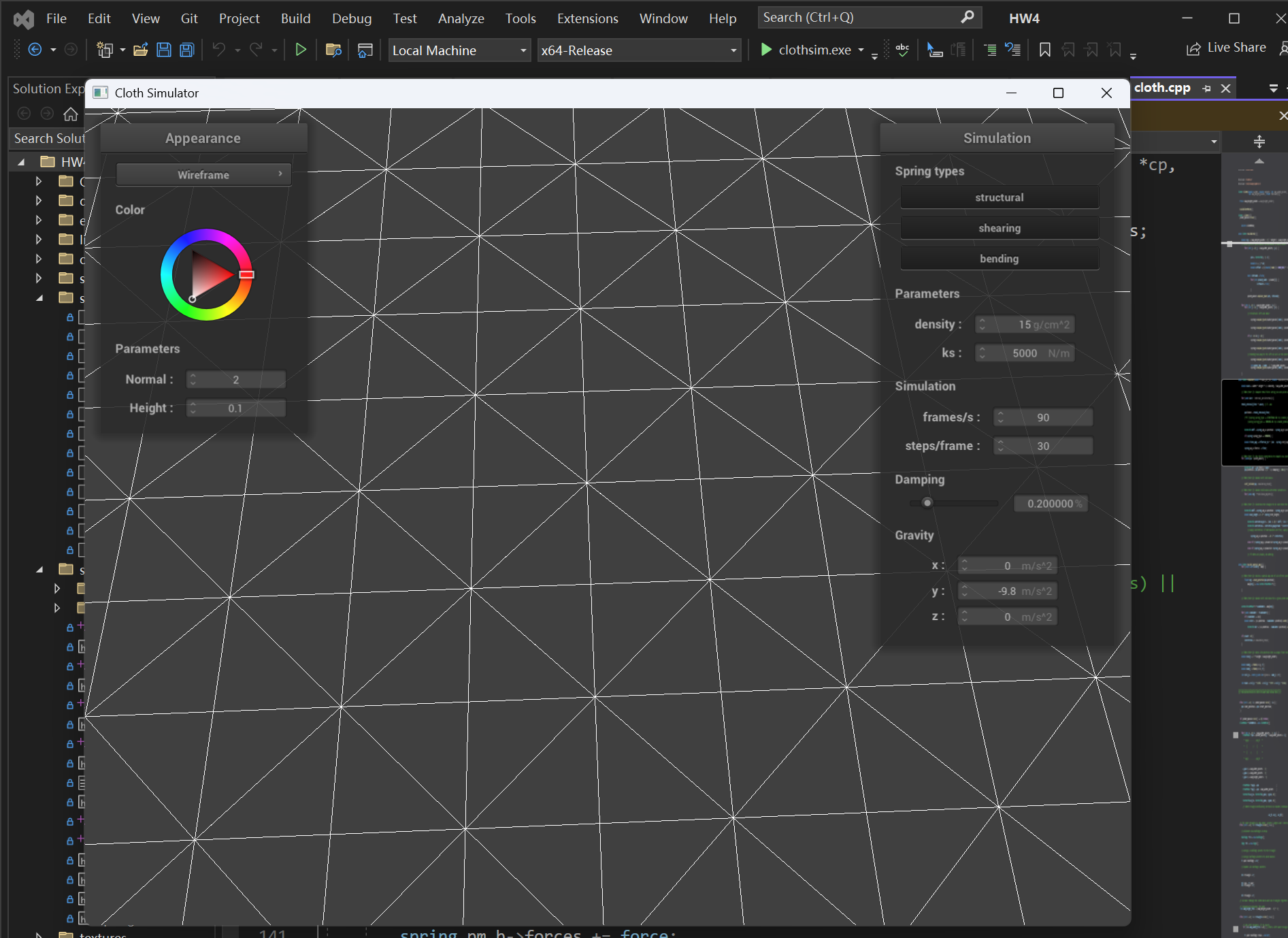
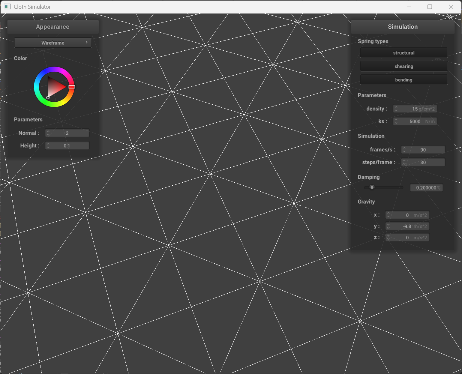
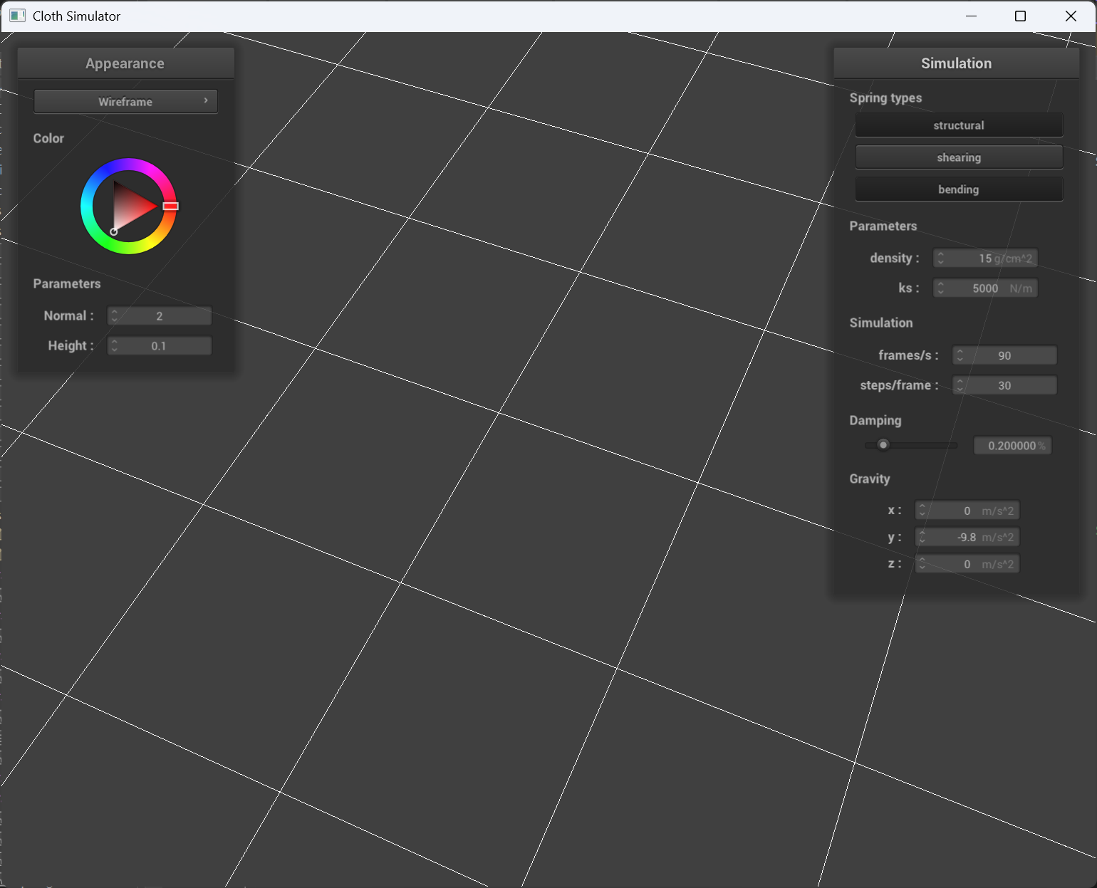
The wireframe screenshots
 |
 |
 |
|---|---|---|
| w/ all constraints | w/o shearing | w/ only shearing |
Part 2: Simulation via numerical integration
Experiments with some the parameters in the simulation
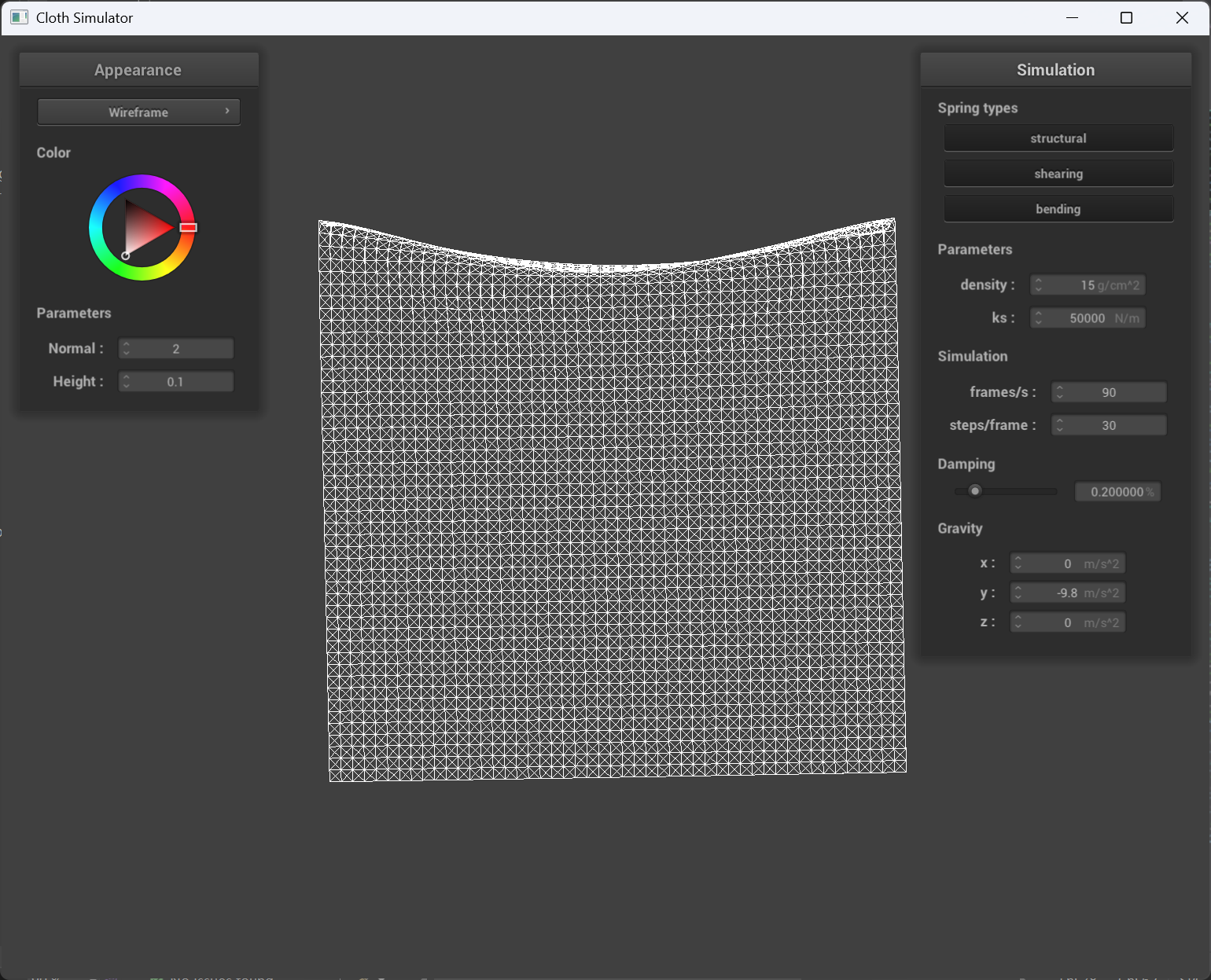
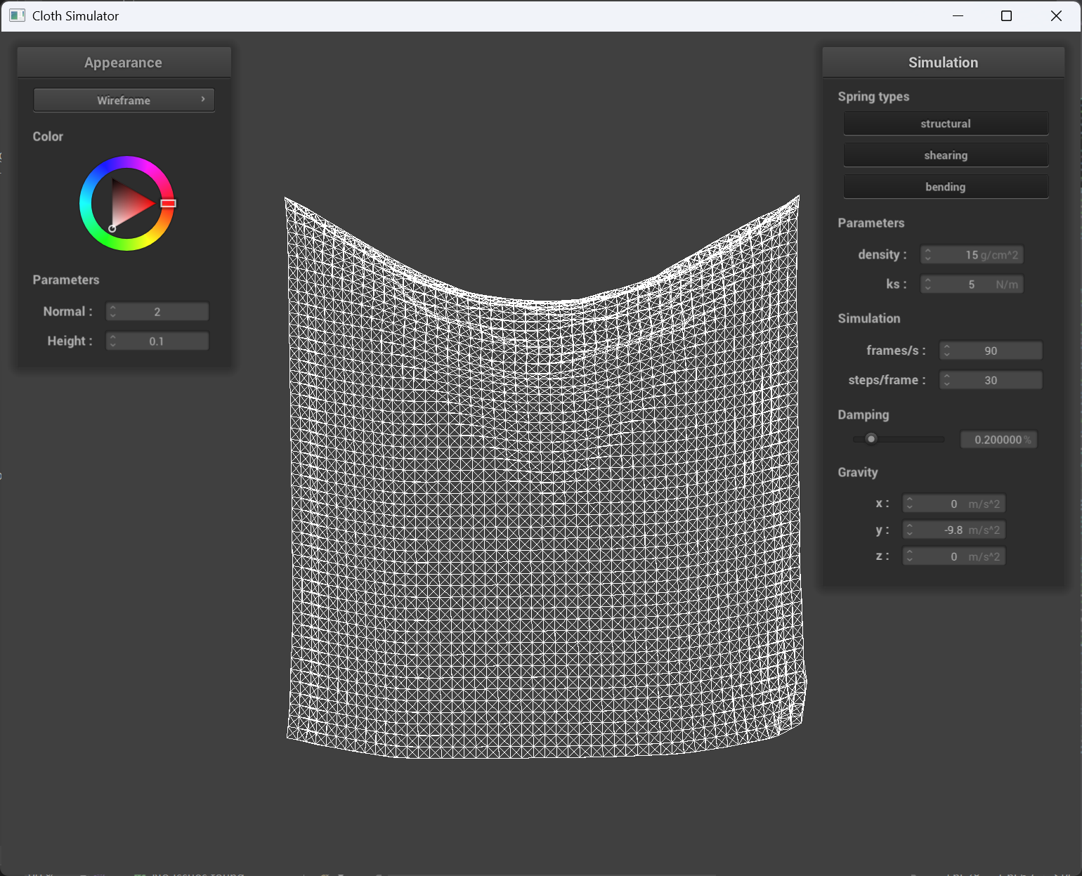
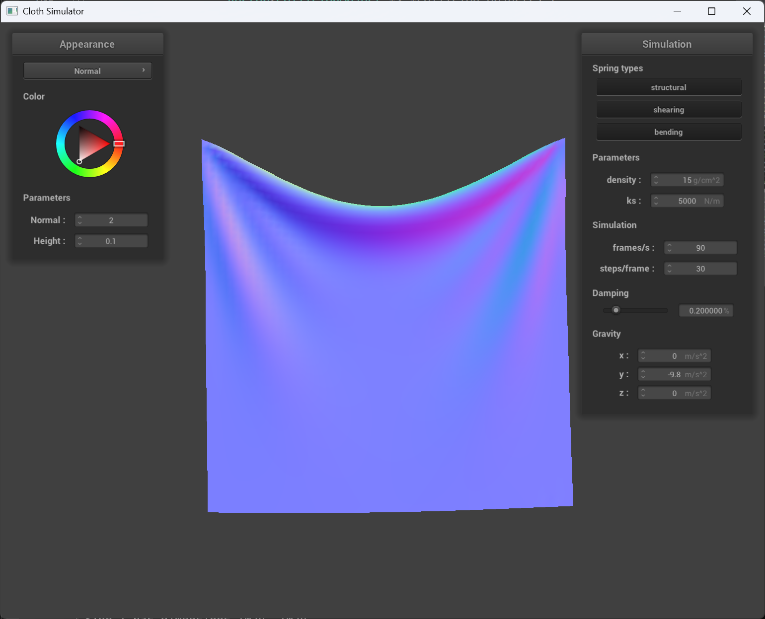
Spring constant ks
When the ks is very small, the cloth behaves very “loose” and tiny little force will make the whole cloth moves and “shivers”. When the ks is very big, the cloth behaves very “tight” and sags less than smaller ks, the whole cloth will reach to a stop faster than smaller ks.
 |
 |
|---|---|
ks = 50000 |
ks = 5 |
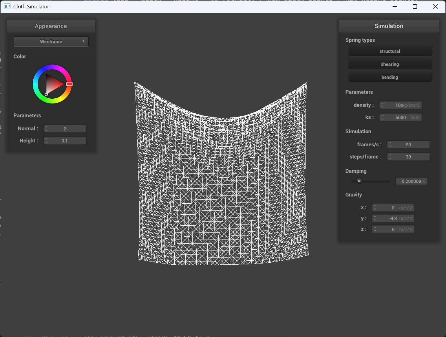
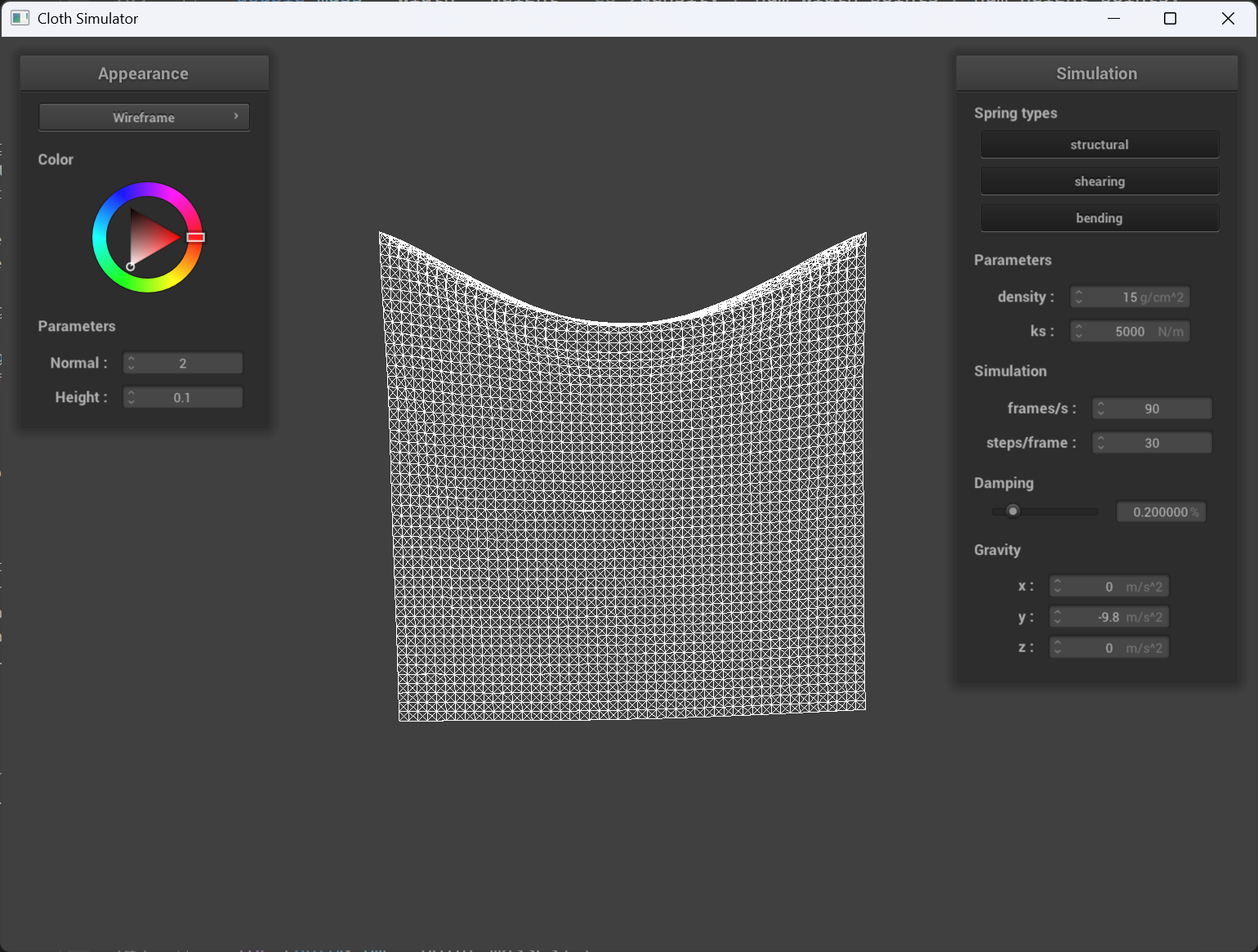
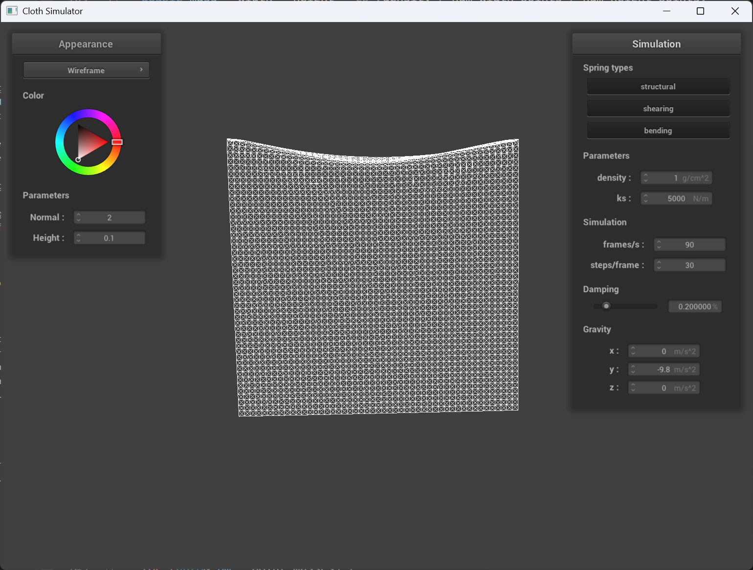
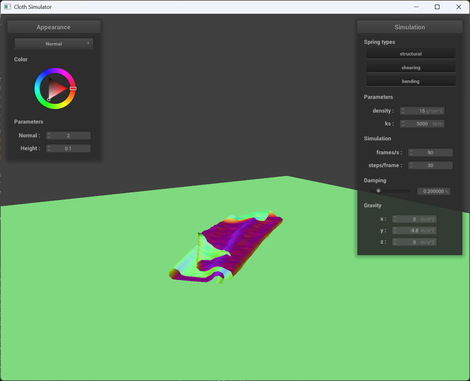
Density
With higher density, the cloth sags more than lower density when at full stop, also, I noticed that when they are dropping down, higher the density, slower the speed, and also the deformation in the middle of the cloth is bigger. This is because the density cause the point mass to be heavier/lighter.
 |
 |
 |
|---|---|---|
density = 100 |
og density |
density = 1 |
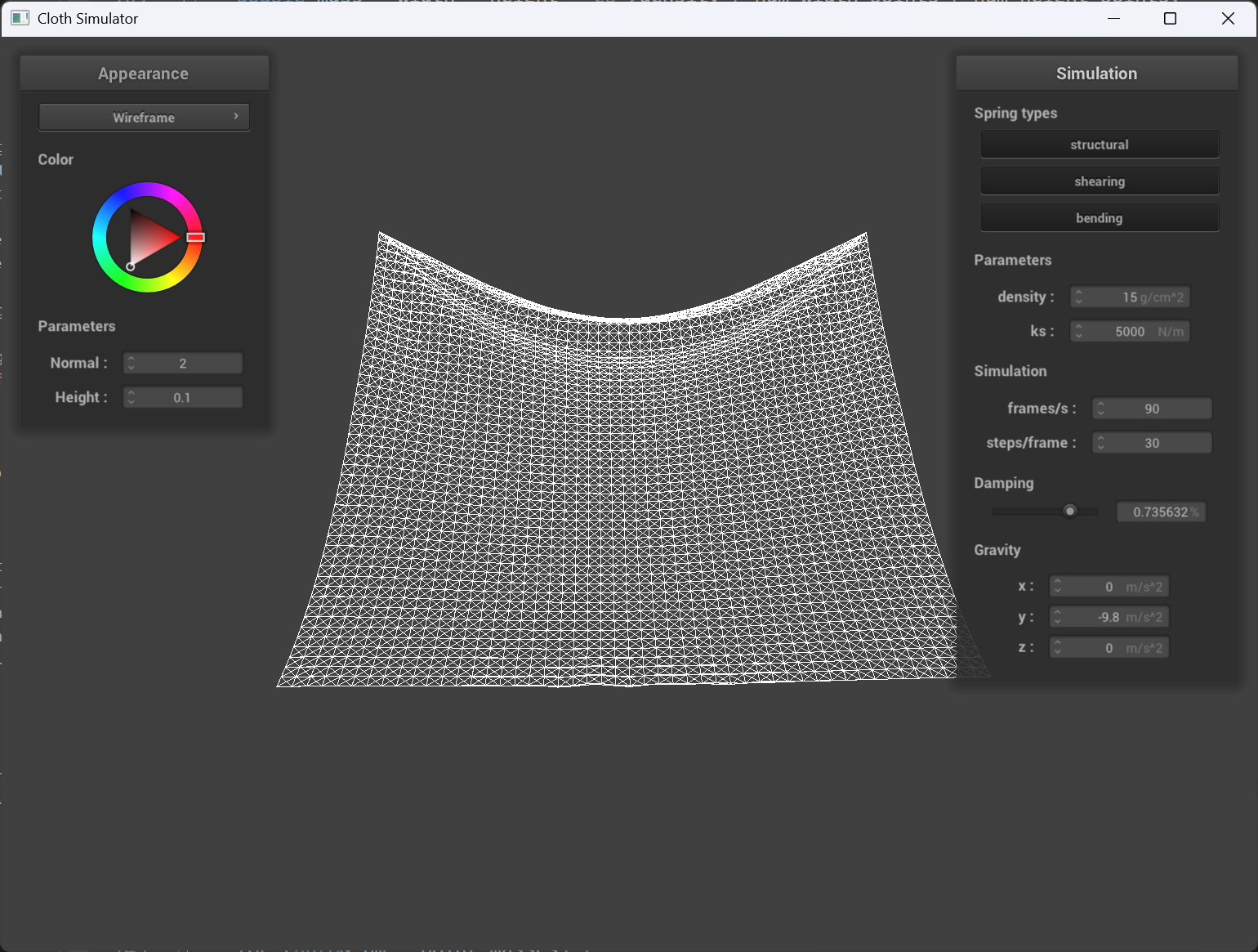
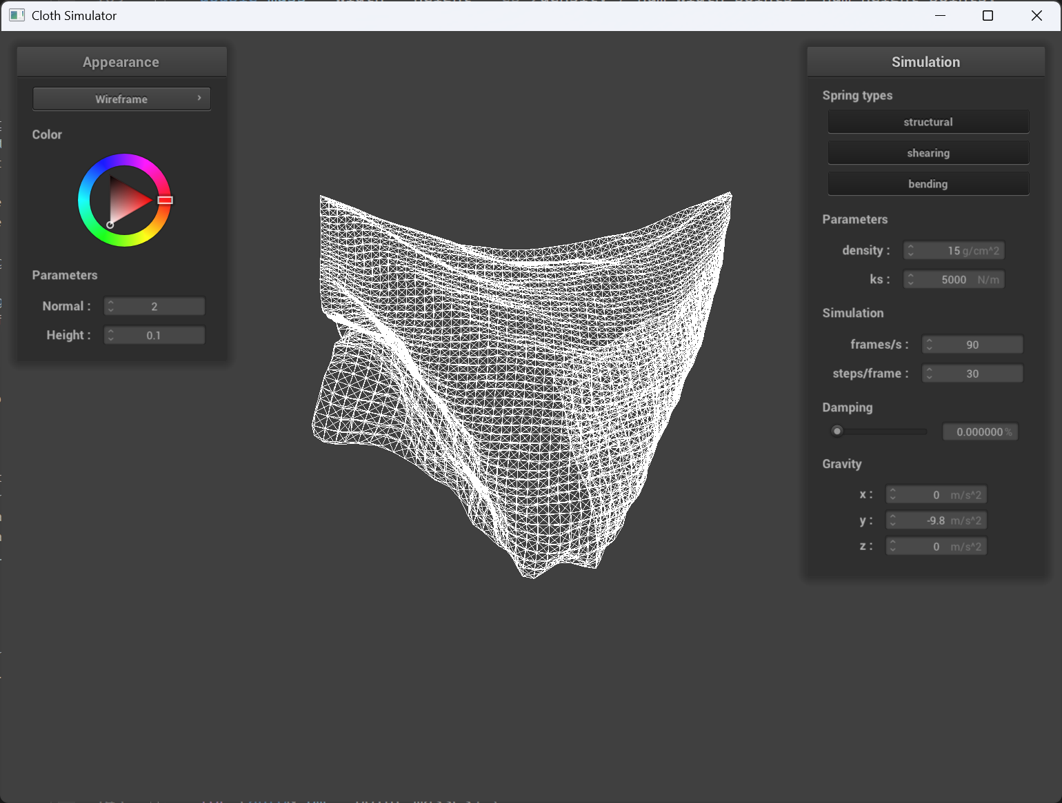
Damping
Bigger damping value results in much stable movement when falling down, which indicates that the delta of point masses location doesn’t change dramatically. From the picture, very low damping value results in the cloth behaves jumping around actively, whereas higher damping value initially controls the cloth movement and then even the sagging speed is lower.
 |
 |
|---|---|
big damping value |
super small damping value |
scene/pinned4.json results
All default.
Part 3: Handling collisions with other objects
Implementation of collisions
Sphere collisions
I first calculate the distance between the pointmass and origin of the sphere’s surface, if it’s landing on it then we just return, if not, I compute the correction vector from the tangent (origin + (dir / dist) * radius) minus last position, scaled down by friction.
Plane collisions
The function first computes the signed distances of the point mass’s last and current positions from the plane by taking the dot product of the difference between the positions and a reference point on the plane with the plane’s normal. If the product of these distances is negative, it indicates that the point mass has crossed the plane. The function then calculates the fraction along the point mass’s trajectory where the collision occurs and determines the exact collision point (referred to as “tangent”) on the plane. Depending on whether the point mass was above or below the plane, it adjusts the collision point by a small offset to avoid numerical issues. Finally, it computes a correction vector that accounts for friction, updating the point mass’s position so that it lies on or near the plane after the collision.
scene/sphere.json results
 |
 |
 |
|---|---|---|
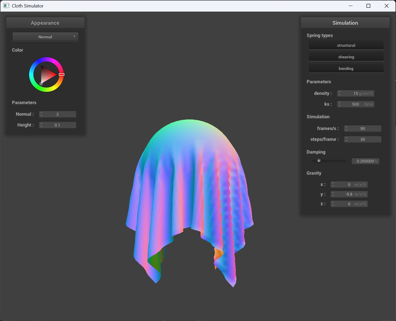
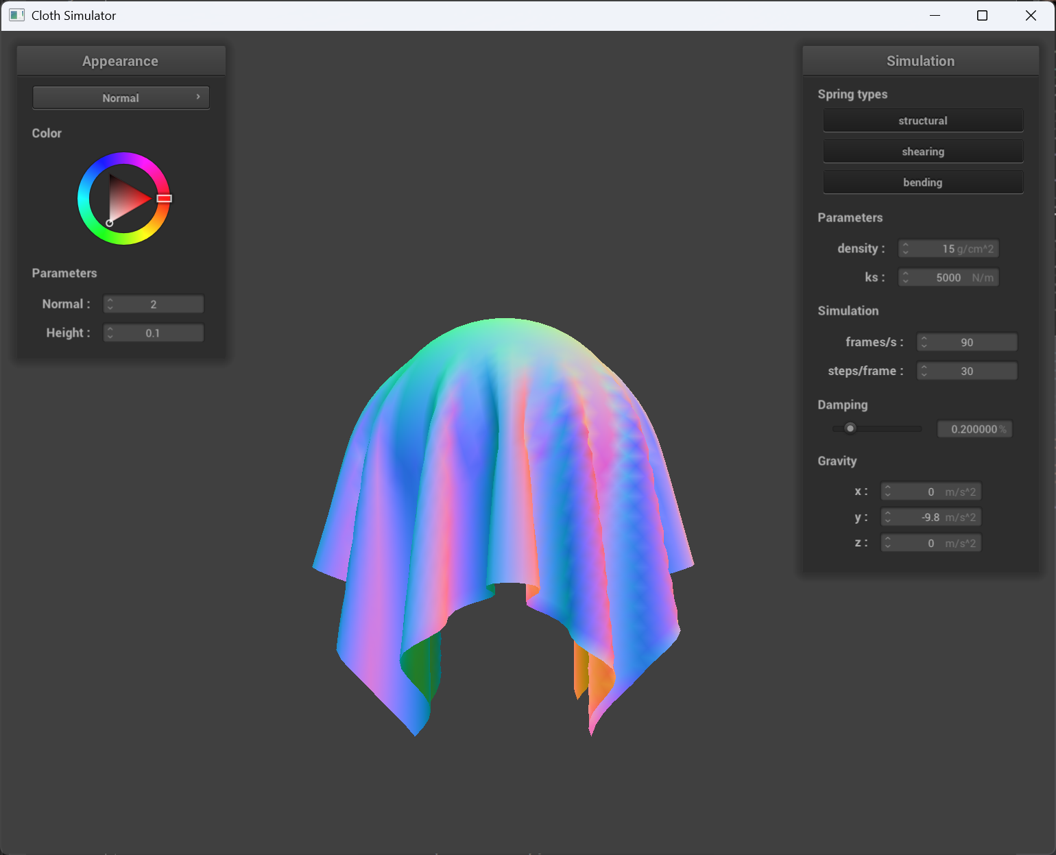
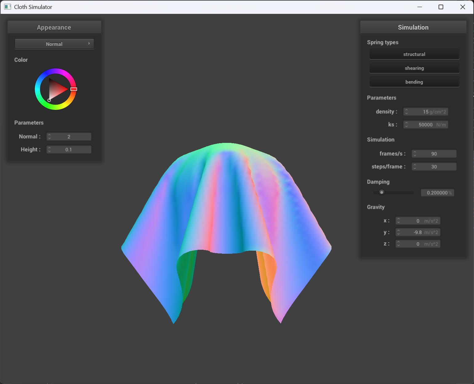
ks = 500 |
og ks(ks = 5000) |
ks = 50000 |
The higher the ks, the cloth seems more “extended” and harder to deform, which matches what ks contributes to the property of the cloth.
Cloth on plane result
Part 4: Handling self-collisions
Implementation of self-coliision
To implement self-collision for the cloth, I used a spatial hashing approach to efficiently detect and resolve collisions between point masses. First, the build_spatial_map function creates a spatial map by iterating over all point masses and hashing their positions into discrete grid cells using the hash_position function, which computes a unique float identifier for each 3D box volume based on the cloth dimensions. Then, in the self_collide function, for a given point mass, I retrieve nearby candidate point masses from the spatial map (i.e., those that share the same hash key). For each candidate (excluding the point mass itself), I calculate the distance between their positions; if it is less than twice the cloth thickness, I compute a corrective displacement vector to push them apart. The average of these correction vectors, scaled by the simulation step size, is then added to the point mass’s position, effectively resolving the self-collision.
Self-collision at different time
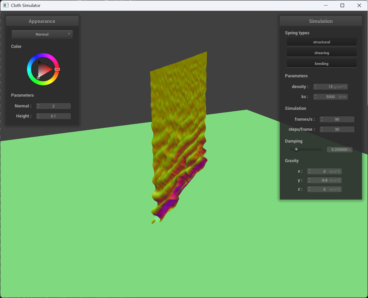 |
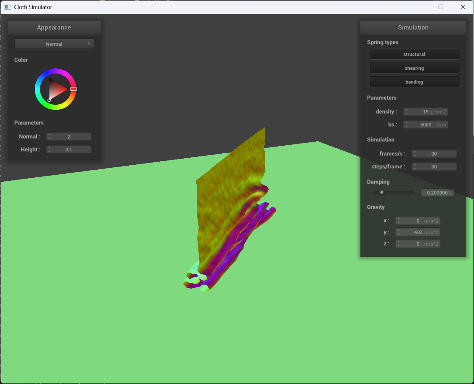 |
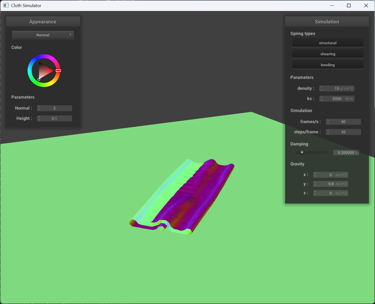 |
|---|---|---|
| early stage | middle stage | near final stage |
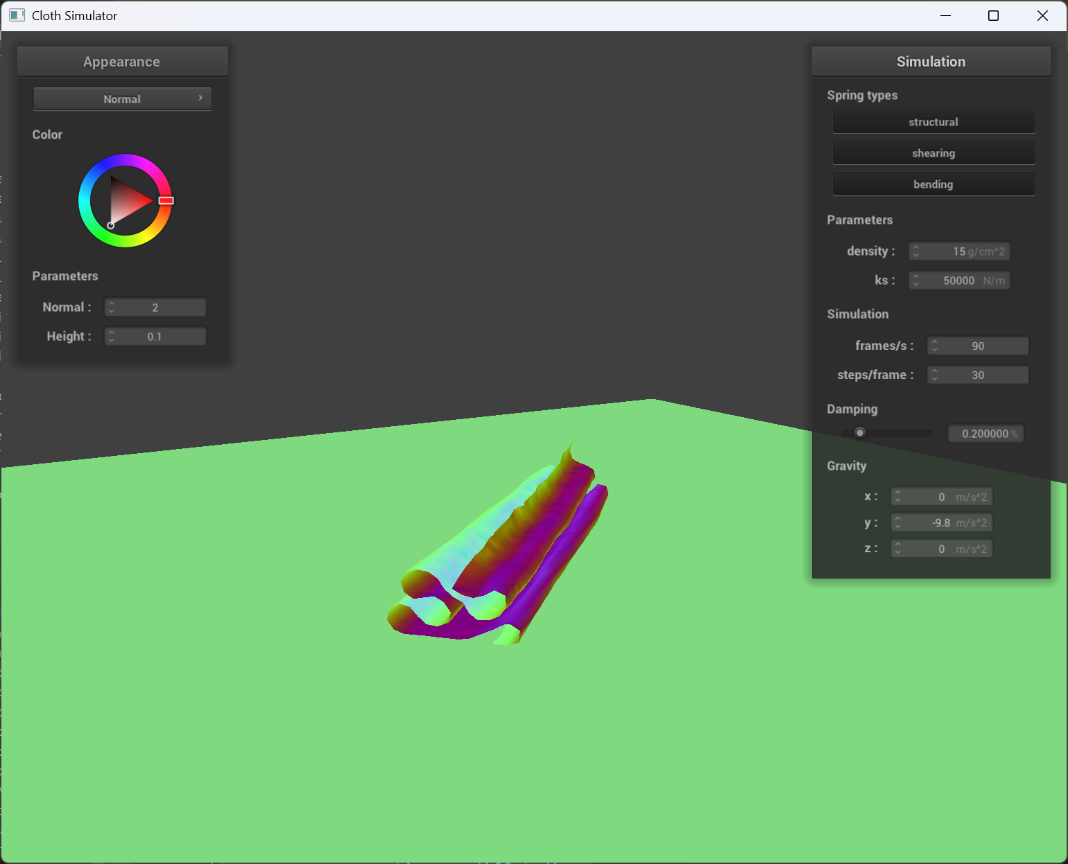
Varied density and ks
 |
 |
|---|---|
og ks(ks = 5000) |
ks = 50000 |
Smaller ks makes the cloth “softer” and there will be more overlapping and creases when cloth falls on itself.
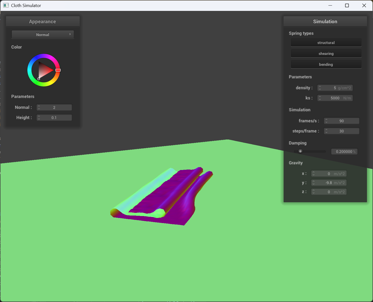
|
|
 |
|---|---|
og density(15) |
density = 5 |
Smaller density makes the cloth more smooth and “flat” when it falls on itself. (Because smaller density causes smaller pointmass weight and individual pointmass won’t fall into the cloth that easily.)
Part 5: Shaders
Shader program, vertex & fragment shaders
A shader program is a set of instructions that runs on the GPU to determine how graphics are rendered on the screen. It typically includes different types of shaders, such as vertex and fragment shaders, that work together to produce the final image.
The vertex shader is the first stage in the rendering pipeline. It processes each vertex of a 3D model, transforming its position from object space into screen space. It can also compute additional data like normals, texture coordinates, and lighting information per vertex.
The fragment shader comes later in the pipeline and operates on each pixel (or fragment) that results from the rasterization of the transformed vertices. It takes the interpolated data produced by the vertex shader and uses it to determine the final color of each pixel by applying textures, lighting models, and material properties. By combining the computations from both shaders, a shader program creates realistic lighting and material effects, making objects appear as if they interact with light in a lifelike manner.
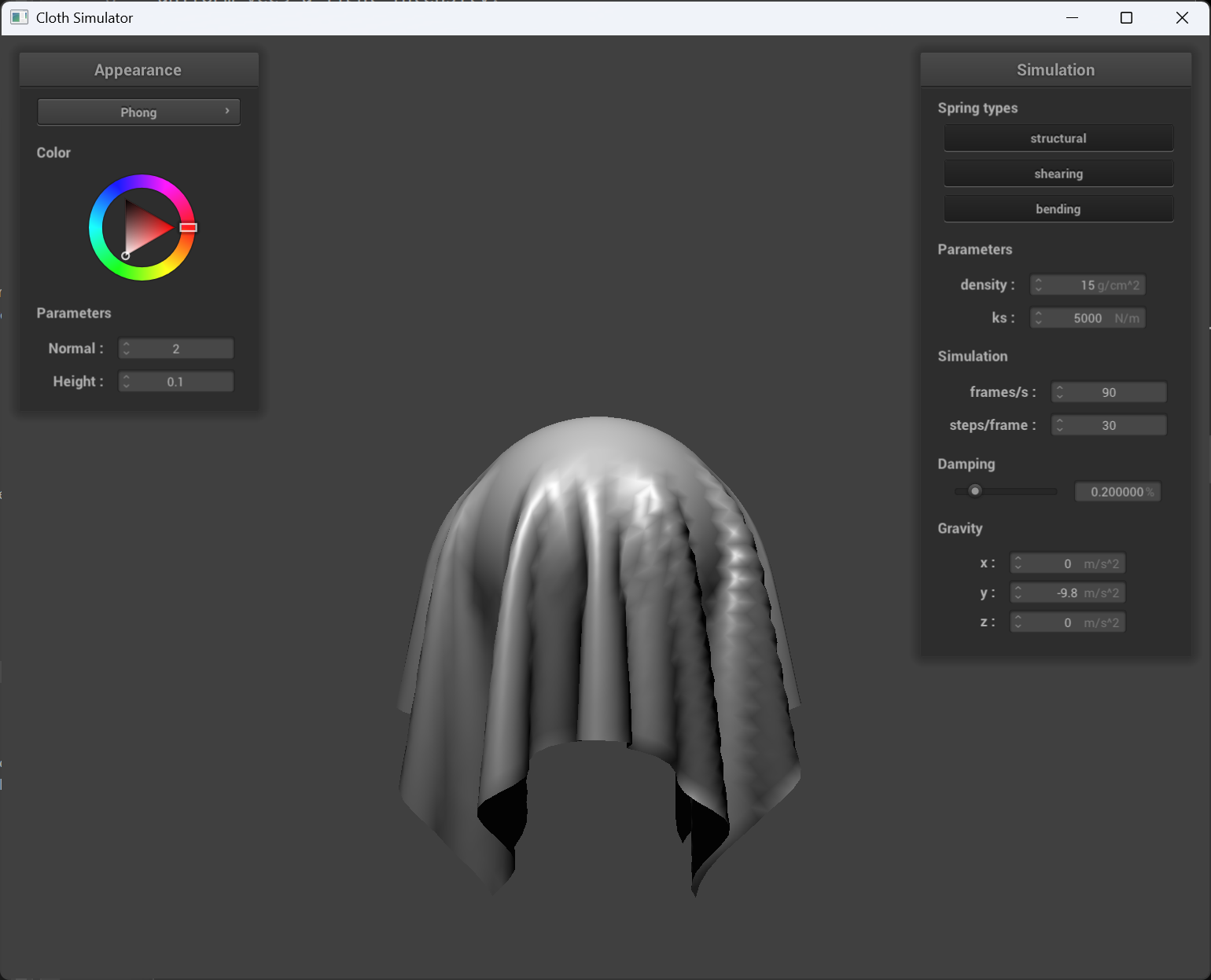
The Blinn-Phong shading model
The Blinn-Phong shading model breaks down the lighting into three main components: ambient light(the constant, background light in a scene that uniformly illuminates all surfaces), diffuse reflection(models how light scatters off a rough surface, depending on the angle between the surface normal and the light direction) and specular reflection.
 |
 |
|---|---|
| only ambient | only diffuse |
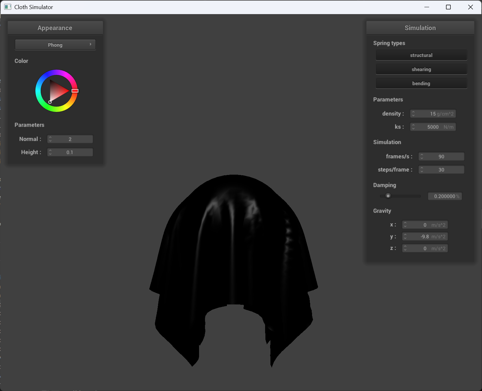 |
 |
|---|---|
| only specular | entire Blinn-Phong |
Texture mapping shader
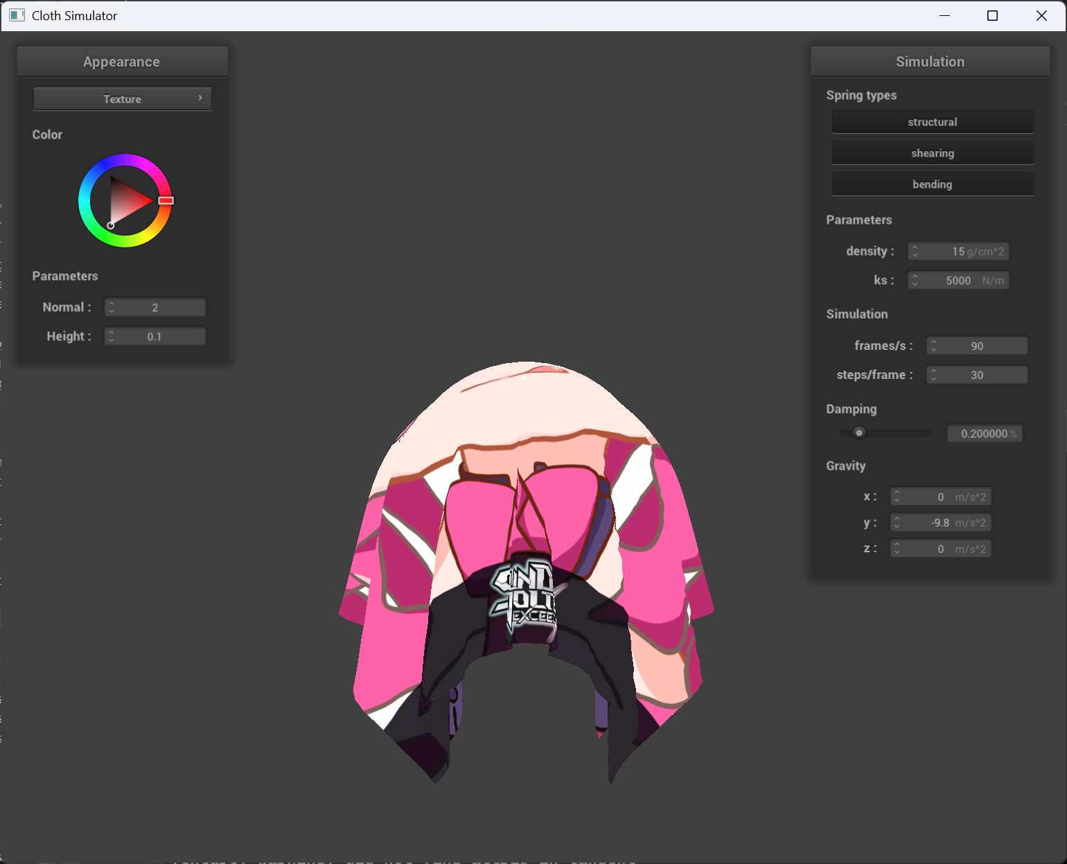 |
 |
|---|---|
| render result | custom texture |
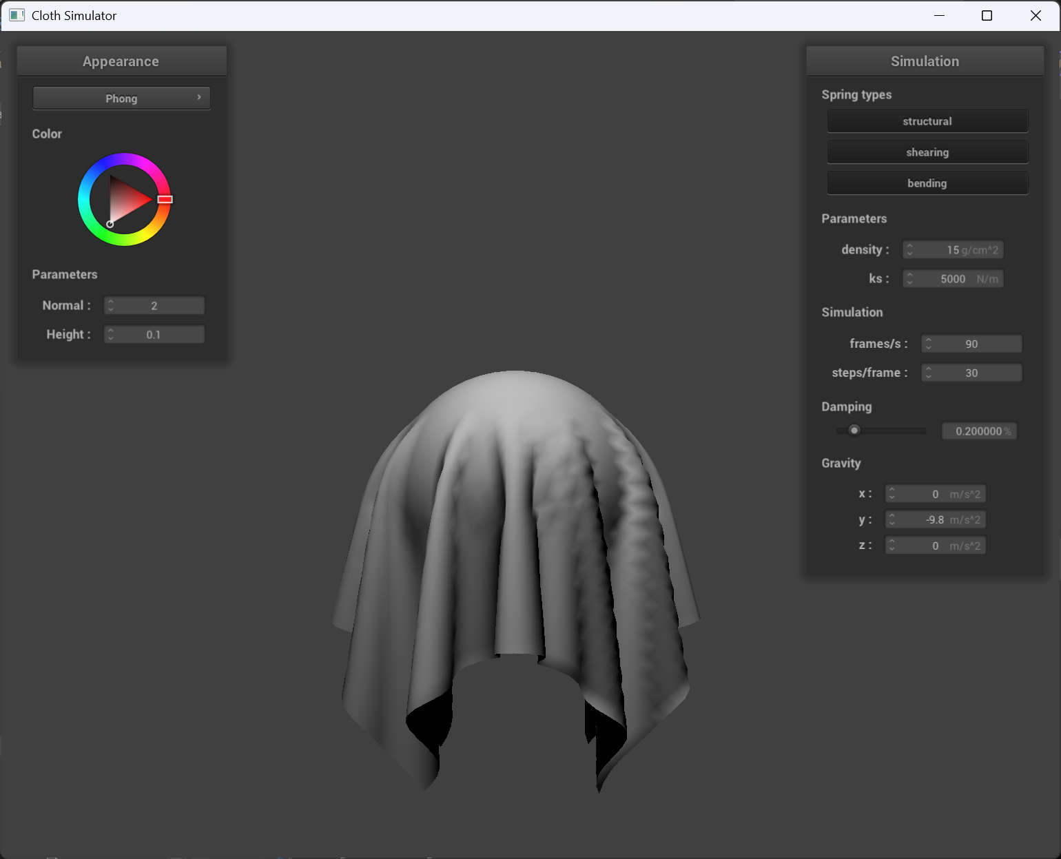
Bump mapping and displacement mapping
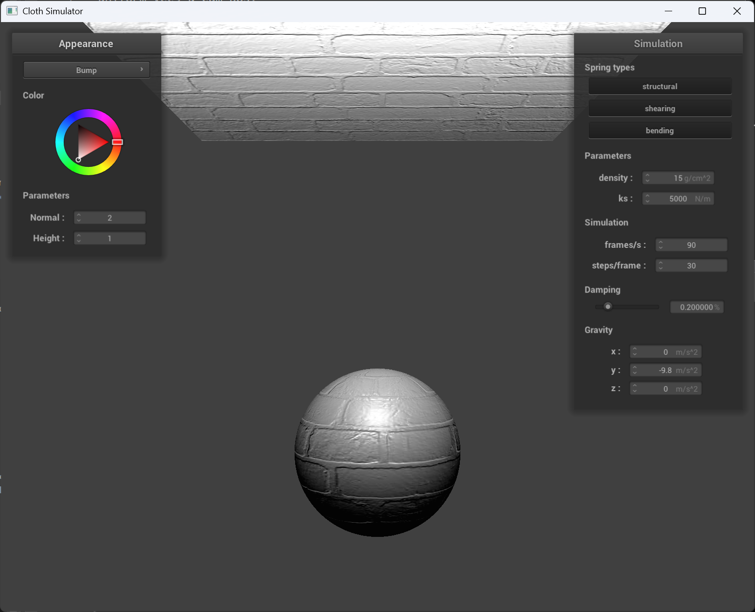
Some results
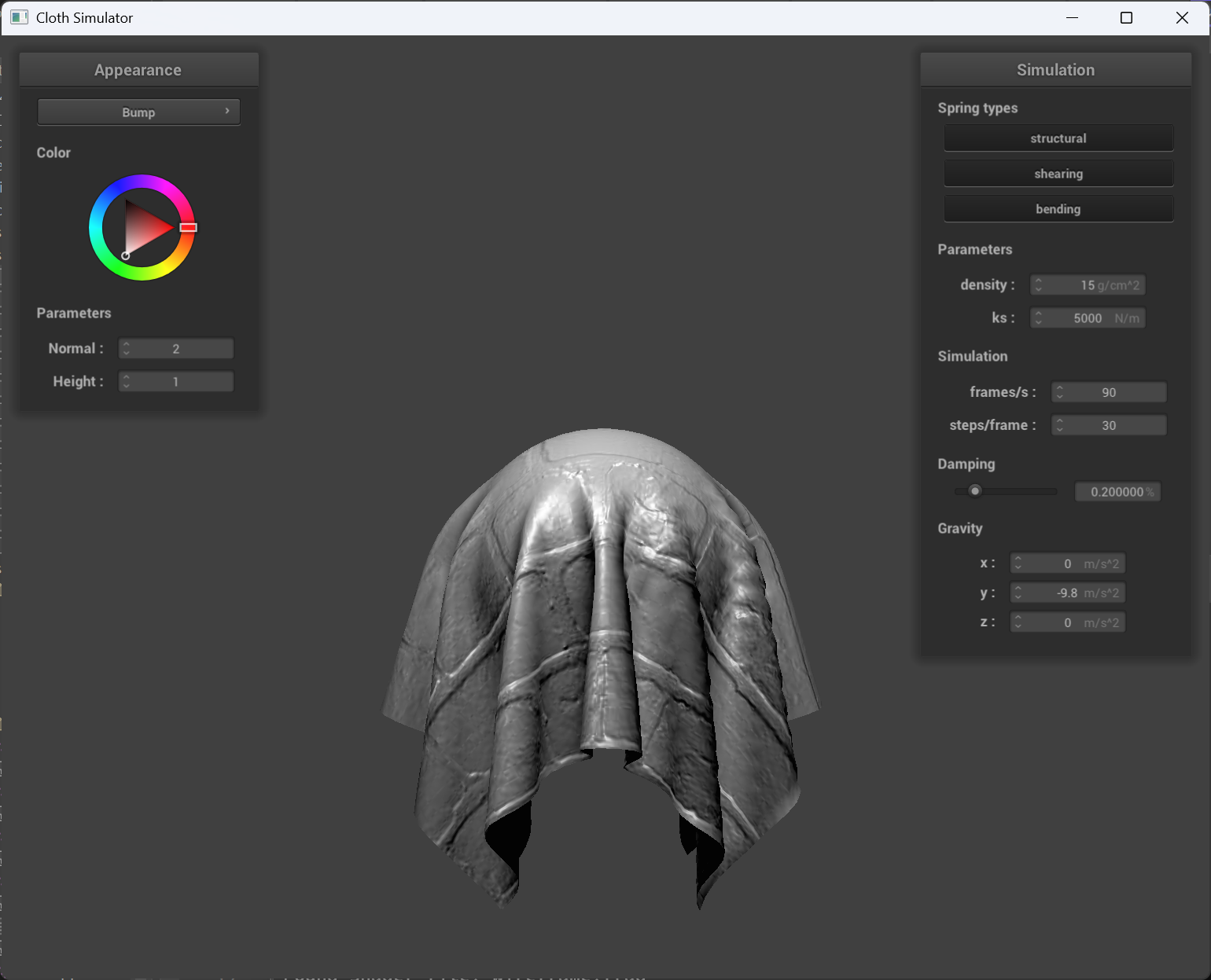
normal = 2, height = 1
 |
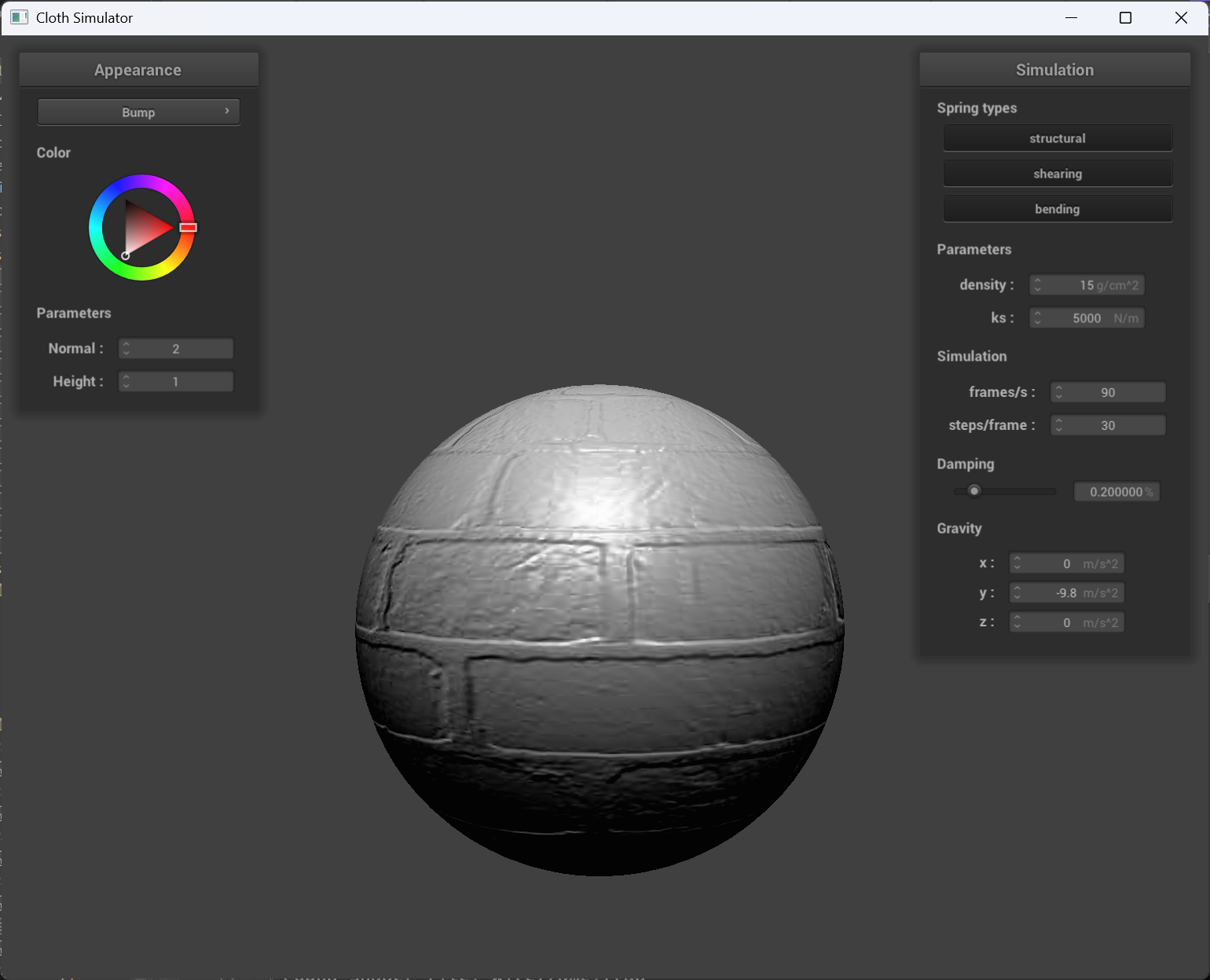 |
|---|---|
| bump mapping cloth | bump mapping sphere |
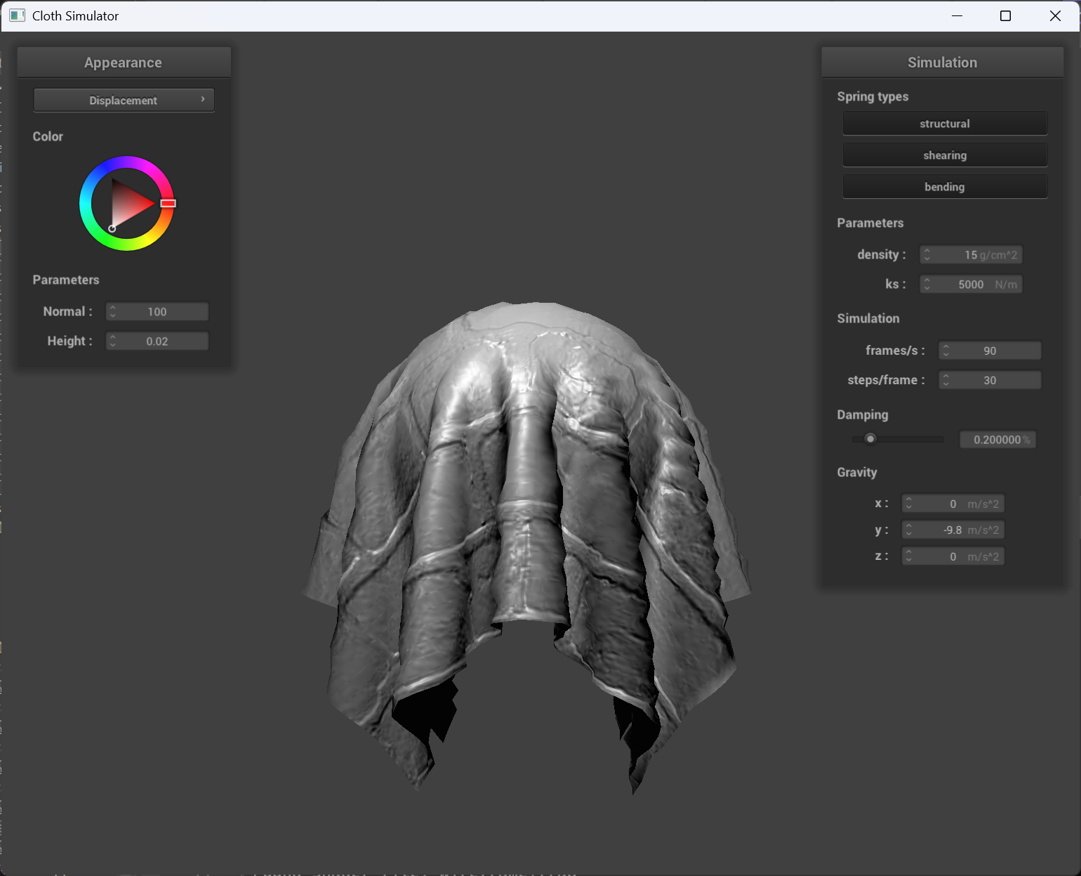
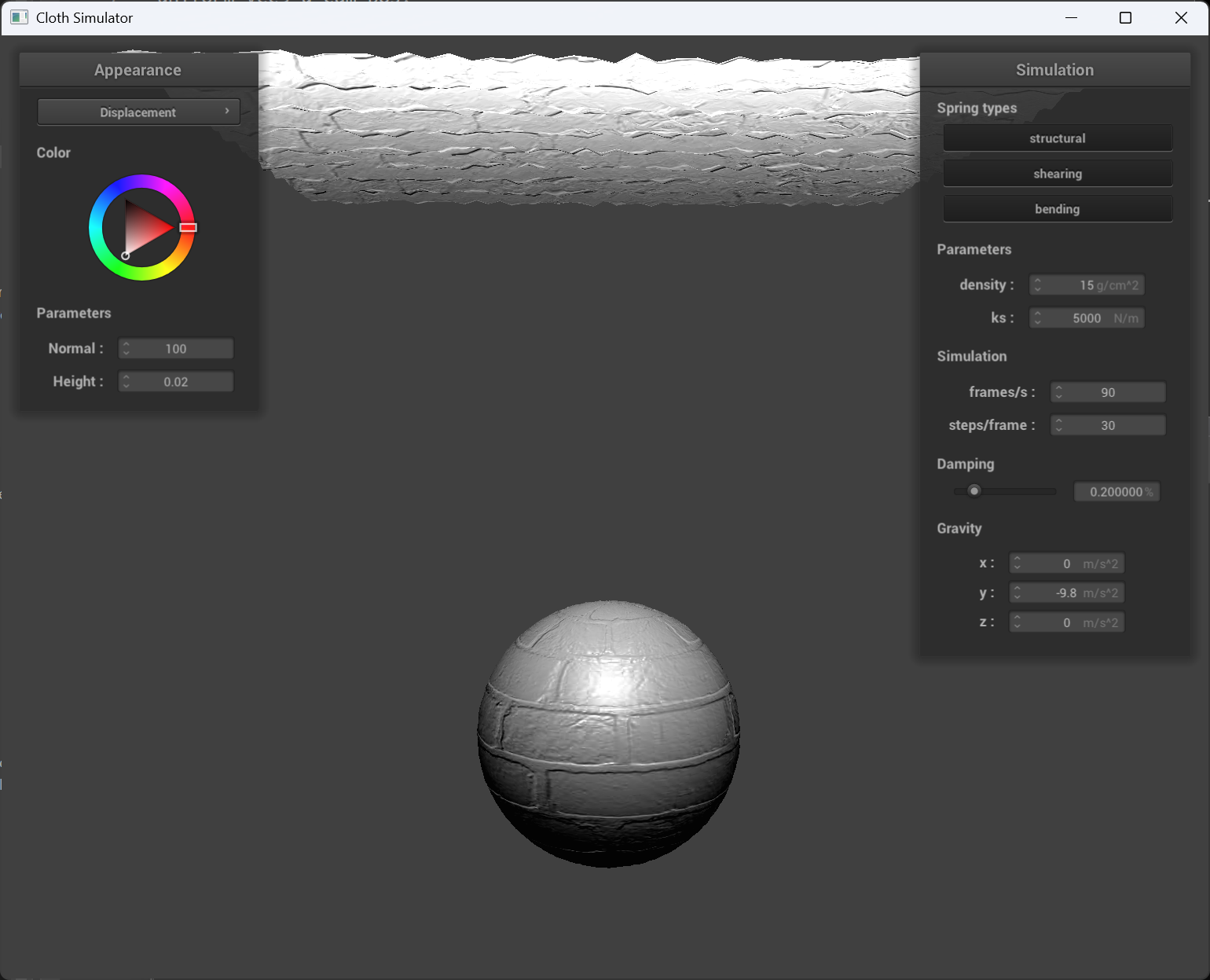
normal = 100 and height = 0.02
 |
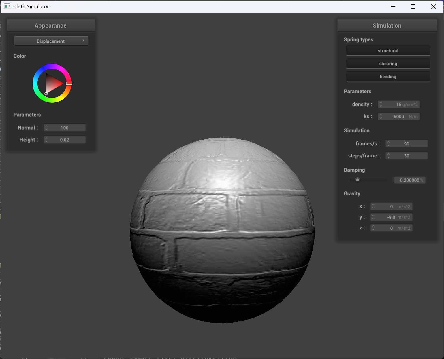 |
|---|---|
| displacement mapping cloth | displacement mapping sphere |
Comparison
Bump Mapping: Bump mapping simulates surface detail by perturbing the surface normals used in lighting calculations, which creates the illusion of texture without modifying the actual geometry. In the screenshots, the cloth shows subtle wrinkles and folds that enhance its fabric appearance, while the sphere exhibits texture detail (such as bumps or grooves) on its surface. However, since the underlying geometry remains unchanged, the silhouette and shadow edges of both objects are not affected by these details.
Displacement Mapping: Displacement mapping, on the other hand, alters the actual geometry by moving vertices along the normal direction based on the texture’s intensity values. In the displacement mapping screenshot of the sphere, you can see more pronounced surface details that not only affect the shading but also modify the object’s silhouette and the way shadows are cast. This results in a more realistic depiction of rough or uneven surfaces, at the cost of additional computational overhead.
Sphere mesh coarseness effect
Above: coarse(-o 16 -a 16), below: fine(-o 128 -a 128).
 |
 |
|---|---|
 |
 |
| bump mapping | displacement mapping |
The bump mapping behaves consistant from coarse to fine, and the displacement mapping sphere is more realistic when it’s fine compared to coarse.
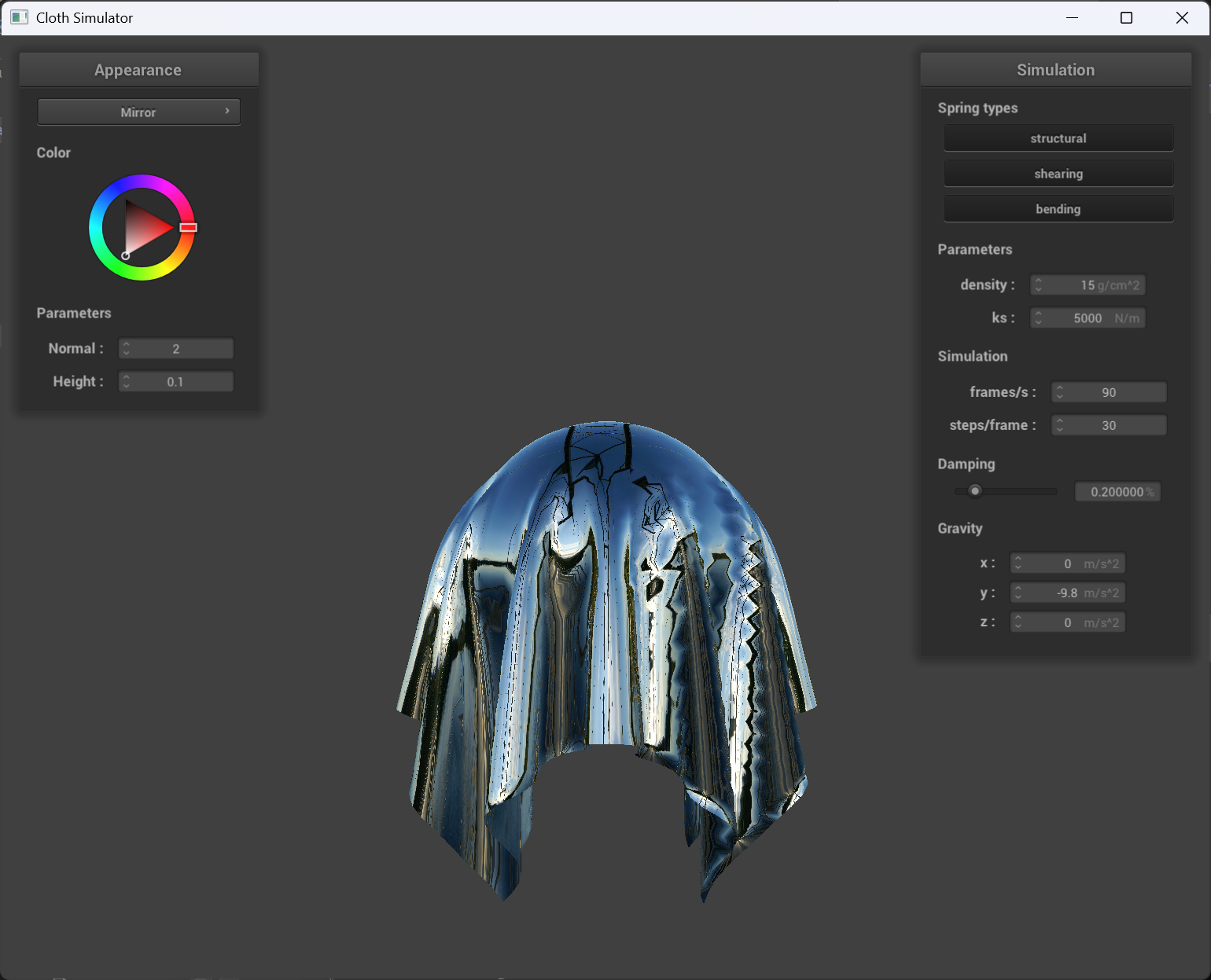
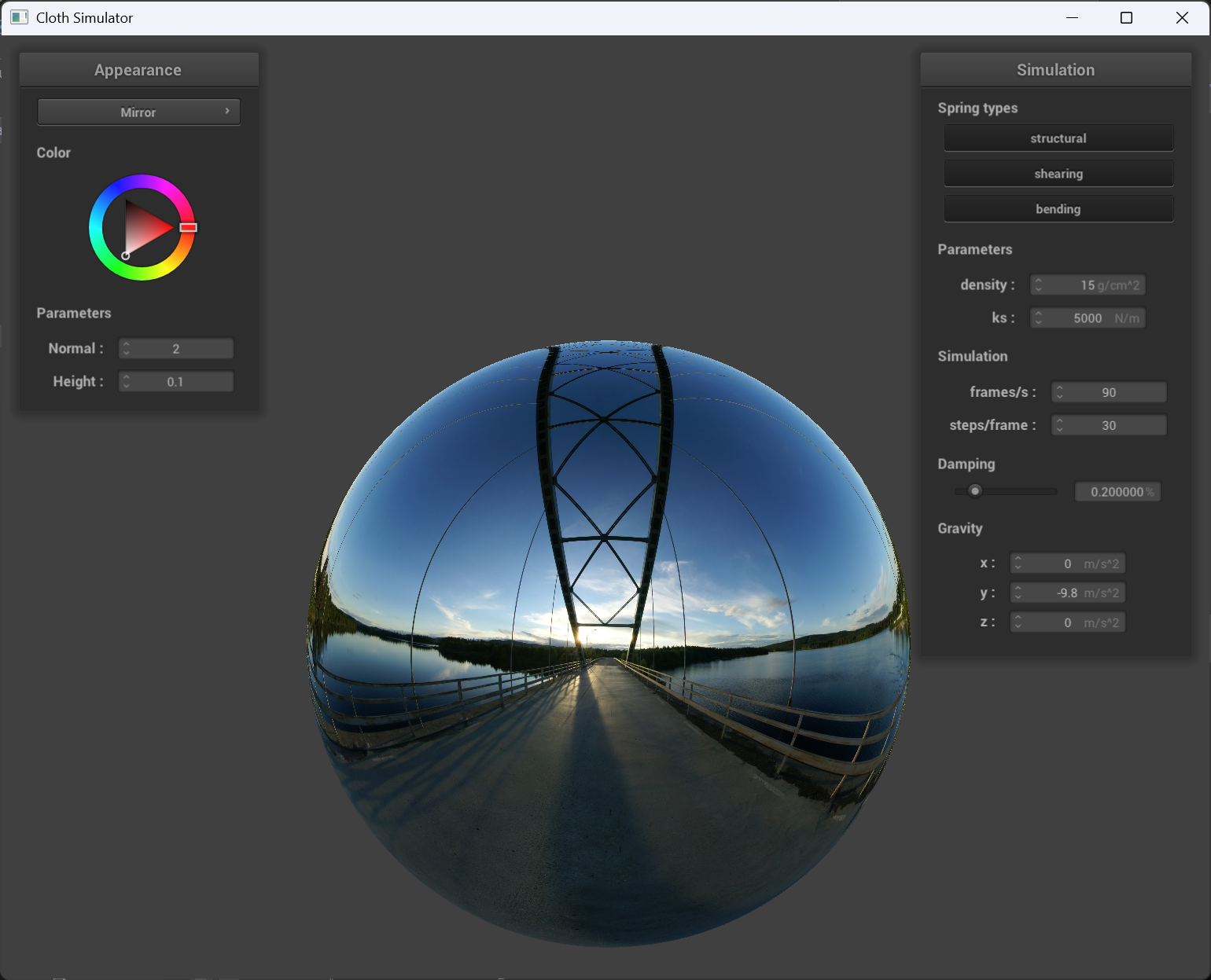
Mirror shader
 |
 |
|---|---|
| mirror shader on cloth | mirror shader on sphere |
Jiashen Du
Undergrad Student major in CS
My research interests include Artificial Intelligence, Deep Learning, Computer Vision and LLMs.